DIGITAL LOGIC FAMILY
DIGITAL LOGIC FAMILY
CMOS Family TTL Family
WHAT IS LOGIC FAMILY
Logic families are groups of logic circuits that are based on particular types of elements (resistors, transistors, and so forth). Families are identified by the manner in which the elements are connected, and, in some cases, by the types of elements used.
CMOS v/s TTL
There are two different types of computer chips: CMOS and TTL. CMOS stands for complementary metal-oxide-semiconductor. TTL stands for transistor-transistor logic. They’re both oftentimes used to make microchips. However, they’re both different and serve different functions. To learn more about the difference between CMOS and TTL, we must understand its functioning.
The difference between CMOS and TTL is that CMOS (complementary metal-oxide-semiconductor) is an electronic component in the logic family. CMOS is used in computers and various other electronic devices. TTL (transistor-transistor logic) is a type of digital logic in the logic family. TTL is also used in computers and various other electronic devices.
CMOS, Or complementary metal oxide semiconductor, uses PMOS and NMOS types of field-effect transistors to handle input and output. They are commonly used in NAND and NOR gates and are economically efficient, and have a higher clock rate making them consume more power than TTL or transistor-transistor logic units.
TTL and Transistor-Transistor Logic Units are made up of BJTs Or bipolar junction transistors that commonly have multiple inputs and outputs. They have a slightly lower density of logic gates and usually are found with NAND gates. However, they consume less power and hence are used in several devices.
Types of Gates
The different types of logic gates and symbols with truth tables are discussed below.
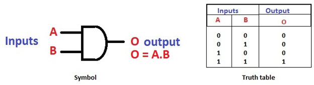
AND Gate
The AND gate is a digital logic gate with ‘n’ i/ps one o/p, which performs logical conjunction based on the combinations of its inputs. The output of this gate is true only when all the inputs are true. When one or more inputs of the AND gate’s i/ps are false, then only the output of the AND gate is false. The symbol and truth table of an AND gate with two inputs is shown below.
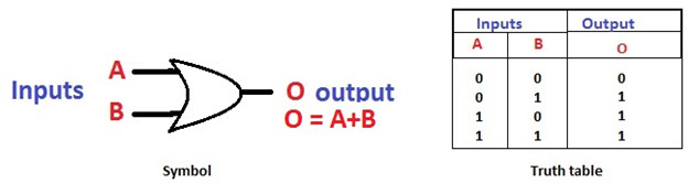
OR Gate
The OR gate is a digital logic gate with ‘n’ i/ps and one o/p, that performs logical conjunction based on the combinations of its inputs. The output of the OR gate is true only when one or more inputs are true. If all the i/ps of the gate are false, then only the output of the OR gate is false. The symbol and truth table of an OR gate with two inputs is shown below.
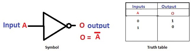
NOT Gate
The NOT gate is a digital logic gate with one input and one output that operates an inverter operation of the input. The output of the NOT gate is the reverse of the input. When the input of the NOT gate is true then the output will be false and vice versa. The symbol and truth table of a NOT gate with one input is shown below. By using this gate, we can implement NOR and NAND gates.
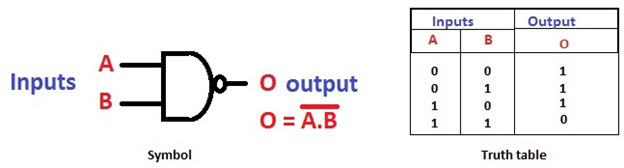
NAND Gate
The NAND gate is a digital logic gate with ‘n’ i/ps and one o/p, that performs the operation of the AND gate followed by the operation of the NOT gate.NAND gate is designed by combining the AND and NOT gates. If the input of the NAND gate high, then the output of the gate will be low.The symbol and truth table of the NAND gate with two inputs is shown below.
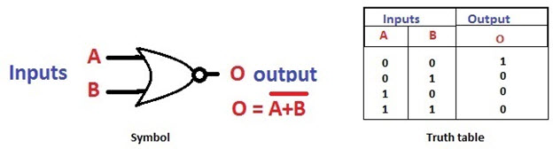
NOR Gate
The NOR gate is a digital logic gate with n inputs and one output, that performs the operation of the OR gate followed by the NOT gate. NOR gate is designed by combining the OR and NOT gate. When any one of the i/ps of the NOR gate is true, then the output of the NOR gate will be false. The symbol and truth table of the NOR gate with the truth table is shown below.
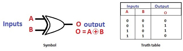
Exclusive-OR Gate
The Exclusive-OR gate is a digital logic gate with two inputs and one output. The short form of this gate is Ex-OR. It performs based on the operation of the OR gate. . If any one of the inputs of this gate is high, then the output of the EX-OR gate will be high. The symbol and truth table of the EX-OR are shown below.
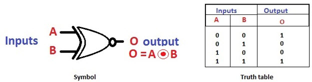
Exclusive-NOR Gate
The Exclusive-NOR gate is a digital logic gate with two inputs and one output. The short form of this gate is Ex-NOR. It performs based on the operation of the NOR gate. When both the inputs of this gate are high, then the output of the EX-NOR gate will be high. But, if any one of the inputs is high (but not both), then the output will be low. The symbol and truth table of the EX-NOR are shown below.

Comments
Post a Comment